-40%
1965 NOVEMBER - STEELWAYS MAGAZINE CUTLERY, HELICOPTER, MODELMAKING HORSE TROLLY
$ 11.43
- Description
- Size Guide
Description
1965 NOVEMBER – DECEMBER STEELWAYS MAGAZINEAMERICAN
IRON
AND STEEL INSTITUTE
8 ½” X 11”
24 pages
USED.
Right corners a bit bent.
Some faint stain on an inner page or two at the binding.
CONTENTS
.2.
Edge
& Appetite
.6.
Look Skyward, Builders
.11. Figuring a Better life
.16. Everything Comes Up
Roses
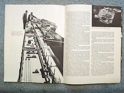
.20. Steel Models Its Future
.24. Sic Transit
Hold The World In Your Hand
Have you ever known anyone who was not fascinated by miniatures?
Surely not, for nearly all people have planned, studied or worked with models, or at least admired them.
There is something compelling about an object, a system or a world n miniature that engages the fancy.
Long ago Egyptian kings were laid in their tombs with ship models ready for their voyage ‘round the polar stars, and such practical models as weaving shops and potteries to assure them all their accustomed comforts in their next life.
What small boy has not relieved the struggles and triumphs of some past inventor by carefully cutting and gluing together a detailed miniature?
And what small girl, emulating her mother, has not spent delighted hours using a doll-size set of china?
Nor do these hobby interests stop at childhood.
Trains, ships, planners and autos all have their devotees banded into clubs, catered to by specialty manufacturers and served by their very own special periodicals.
These organized pursuits are a far cry from a solitary old salt whittling and rigging a model of his favorite ship.
But not all grown-ups make models for pastime; within the steel industry deftly crafted models prevent problems.
They perform vital services testing production lines and simulating new ideas.
( Our
cover depicts some Lilliputian equipment for steel plant models. )
Problems disappear, too, as young marrieds, heads together over the kitchen table, dream their dream house into miniature reality with a paste-and-cardboard model.
Here it is decided whether the dryer will fit next to washer and sink, or where the nursery will go.
Now, the season hastens toward us when that model of all models venerated by the western World reappears.
Again, in a hundred scales of carved, cast and molded miniatures we will behold the mute and eloquent re-creation of the event in Judea.
The
Child, the marveling parents, the reverent kings and the humble beasts will assume their places around the wondrous nativity tableau and make it the perpetual model for adoration.
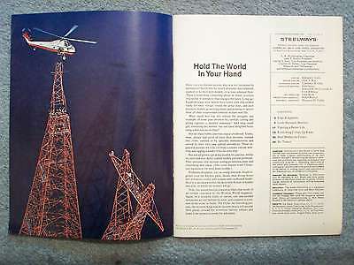
CAPTION:
New York horse for contractors hovers high over steel along the Hudson River.
Article on helicopters begins page six.
Edge & Appetite
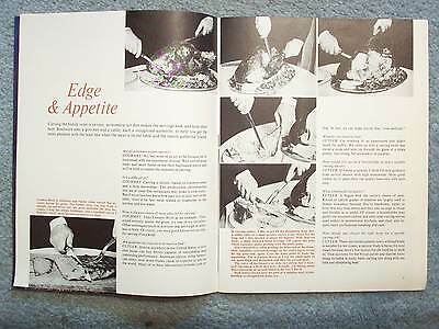
Carving the family roast is an easy, economical act that makes the servings look and taste their best.
Steelways asks a gourmet and a cutler, each a recognized authority, to help
you get the most pleasure with the least fuss when the meat is on the table and the family gathered ‘round.
CAPTIONS:
London Broil is delicious and tender when carved this section across the grain.
The farther away you stay from a straight up-and-down cut, the more desirable the slice becomes.
Using this simple technique, and a standard carver I find this “hard” meat becomes a treat every time.
In carving turkey,
I like to get all the disjointing done first.
A utility knife or a small poultry carver is my choice for the wing and I slice inward at about45 degrees. With that cut made, a slight outward blade leverage will expose the joint which separates under probing with the knife point.
One vertical slice, while holding the bone-end of the drumstick, simplifies outward leverage on the entire leg to reveal the hip joint and, again, I use the knife point to make the separation.
The
technique shows as I use the small knife cut apart thigh and drumstick and slice the second joint.
The curve of the
breast is so close to the vertical that it looks as if I’m taking a thick slice here.
Actually, I’m taking about three-sixteenths of an inch which is the way I like it.
Both knives shown here are part of a stainless steel, wood-handled set designed for home use.
A slim carver seemed right for this small leg of lamb, although I’d have used a broad blade for a larger one.
There are several techniques for carving lamb.
I prefer to remove the nub below the shank so that the roast will sit firmly with the bare bone angling upward.
Then I slice down toward the thigh bone, cut the slices off along the length of the bone and lift them out, as shown.
I This same technique is useful with ham.)
Additional slices may then be taken from the sides; in fact many people begin this way.
It produces a variety of grain structures, but lamb is so tender that it doesn’t matter at all.
( Techniques by
Mr. T. Norman Palmer, president, The Society of Gourmets for The Leisure Arts, Inc.)
There’s delicate meat in a rib roast of beef, and it takes a keen edge to carve the very
thin slices I
prefer.
Here, I’m using a professional slicer made of tool steel, although
I’d go to my stainless steel carver and a fork if it was a party occasion.
I took six or seven slices per rib on this roast, and rather than scrape my knife edge against a rib, I stopped short of the bone and made a deep
vertical cut with a boner to free the slices from the ribs and remove them for serving.
CAPTION:
KNIFE SCHEMATIC:
POINT;
EDGE;
SWAGE;
CONCAVE;
BACK;
CHOIL;
RIVETS;
FULL TANG;
BUTT
Look Skyward, Builders
by
FRED SCHNAUE
A steel beam, weighing a ton or more, swings gracefully through three miles of mountain passes.
On the roof of a finished building, steelworkers scurry to pull pipe sections down from the chilly sky and fit them
into the structure’s steam system.
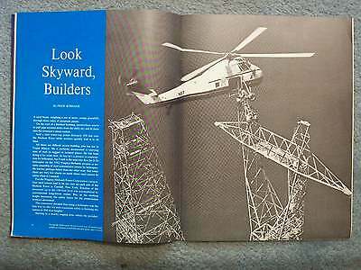
And a steel tower-top poises delicately 300 feet over the Hudson River while workers quickly bolt it to its base.
All these are difficult access building jobs but not to Frank Minjoy.
He is perfectly accustomed to carrying tons of steel to rugged or isolated places.
He has been doing it for years now.
In fact he’s a pioneer in construction by helicopter, for Frank is the man who
flew the S-58 helicopter on the 1962 Niagara-Mohawk project – a notable assembly of steel transmission towers by helicopter.
He knows, perhaps better than any other man, that today there are very few places on earth where steel cannot be taken when it’s wanted.
For the Niagara-Mohawk power Corporation’s project, four steel towers had to be set – two on each side of the Hudson River at Catskill, New York.
Erection of the structures up to the 160-foot level was accomplished by conventional long-boom cranes.
But, as the
working height
increased, the safety factor for the construction workers decreased.
The contractor decided that using a helicopter was the best way to offer his men maximum safety in finishing the towers to 306-foot heights.
Starting at a nearby staging area –where
the
prefabricated top sections of the towers were laid out on the ground – Frank Minjoy’s helicopter rippled the dust below as it came down to pick up the steelwork.
A cable was lowered by
winch, the steel was secured to the line, and Minjoy pushed forward on the stick as the machine rose in the air gently carrying its cargo to the construction site.
Below, workers watched as the “wooping”: sound of the eager eggbeater faded in the distance.
Stretching taut from the machines belly, the wire rope held the frame over the partially completed tower and then planted it precisely on the structure itself where nine workers reached to steady the pinnacle section and quickly bolt it into permanent position.
The scissor-hooks on the end of the cable were then released and Frank maneuvered his “chopper” carefully away from the structure, to return to the staging area for another trip.
CAPTIONS:
Chopper lowers ventilating unit
onto steel mill roof while workers maneuver it into
place.
Steel cable is then released.
Model 240B turbine-powered helicopter delivers galvanized steel beam for use in
construction
of water flume.
Southern California Edison Company entailed the reconstruction and new installation of a system of water flumes leading from a lake, over canyons and through tunnels, to a power house which generates and sends electricity to substations for distribution to residential areas.
ONE OF THE LARGEST HELICOPTER manufacturers is currently producing a “flying
crane” which is being used by the Army.
The machine can easily lift 10 tons – which is
three times the payload average helicopters are capable of lifting.
A commercial version of the big crane is several years off but the manufacturer feels that once quantity production is achieved for the military the price of the machine will be lowered and, as a result, it will become within the financial reach of contractors or helicopter operators.
The United States Army uses its flying cranes to pick up specially
designed pods, carrying 87 troops comfortably.
Upon landing and detachment – which takes only a matter of minutes – the pod
can be used for a field control point, radio center or even hospital.
The ‘copter has been used to carry trucks and bridge sections – feats which have obvious value
in industry and construction.
The praying mantis looking machine appears to straddle its cargo between giant, awkward looking egs.
With the cargo securely attached by a hook or cable to the big ‘copter’s belly, the tremendous machine
dwarfs its load as it lifts it effortlessly above the tree tops.
The big ‘copter climbs at the rate of
1,500 feet per minute in comparison to the 1,000 feet per minute of conventional craft.
In spite
of the
increased speed in
vertical liftoff, there is no
difference in the physical sensation experienced – both
feel like ordinary elevators when they rise.
The flying crane is the forerunner of large craft to come.
In the future helicopters of this size, and of even greater lifting capacity and longer range, will be used ot move sections
of prefabricated homes to assembly site or transport bulldozers to hard-to-reach
construction areas.
The crane is built so the pilot of the craft actually has two different seats and vantage points.
In addition to the seat in the front of tea bin, a seat facing the rear of the craft gives an unobstructed view of all sides and below.
The pilot can observe and make the precise maneuvers that may be needed on a job of, say, planting a prefabricated roof section
on a house.
The flying crane is a realization of the dream off Igor Sikorsky, the gentleman credited with
flying the first successful helicopter on September 14, 1939.
Mr. Sikorsky, now 76 and still active in aircraft engineering, flew his prototype over the streets of Stratford and Bridgeport, Connecticut, on that summer day twenty-five years ago.
There is the story of the man walking down
the street hearing the noise of the helicopter overhead.
Looking up he saw the strange looking bird with Sikorsky at the controls smiling down at him.
The man then noted a small boy peering skyward and asked him what thee thing was.
“That’s Sikorsky’s helicopter,” the boy said.
“What’s it do?” the man asked.
“That’s what he’s trying to find out,” the boy answered.
What Mr. Sikorsky found out as a result of that
first flight and the many others that followed has been put to use by imaginative and progressive industrialists in doing a better job for themselves and their customers.
CAPTION:
The “flying crane” starts to lift off with a bridge section securely attached to its belly.
Machine, currently used by the Army in Viet Nam, can carry a ten-ton payload.
Figuring a BETTER LIFE
…
a)
the average hourly wage in steel is .82 and employee benefits in addition to that sum average 65.5 cents an hour – a total employment cost of .48 and b) wage earners in steel are working an average of about 38 hours a week….
Steel wages have been trending consistently upwards for 25 years and have risen faster than wages in all manufacturing over the same 25 years.
…
Last year the GNP came to 8.7 billion; the total contribution of companies in the iron and steel industry was only about 2 percent of GNP, as shown in the chart on page 13.
…
Statistical experts often frighten away laymen like Mr. Potter by using descriptive language that becomes intricate so as to be precise.
“It’s wrong for a person to avoid a subject completely because he doesn’t understand all its complexities,” says one statistician.
“After all, millions of people appreciate complicated music while knowing very little about its composition.
In the same way, it’s possible to enjoy some of the fruits of statistical knowledge without being steeped in the processes.
Many schools and colleges teach statistics as a branch
of the humanities and that’s what the subject often is – the use of numbers and symbols to describe cultural matters that can’t be made so explicit in words.
Of course the statistical approach is also essential in many branches of science and engineering.”
EVERYTHING COMES UP ROSES
by Don James
AN OCEAN OF FLOWERS sends a big wave of pleasure around the world each January 1 when Pasadena, California, holds its famous Tournament of Roses.
…
As many as 350,000 fresh flowers – and not one weed or artificial bloom – may be on a single float.
The weight of the flowers is heavy.
As a result, practically every unit in the Pasadena parade has an all-steel framework and chassis.
Even ten years ago 80 percent were so equipped.
Prior to 1945 there was little or no use of steel.
This
unique market has been gained largely at the expense of wood.
Aluminum made an effort to capture the business but failed to do so.
The best estimate of several builders is that an average sized float requires 1 to 1 ¼ tons of steel, while a large float takes 2 to 2 ¼ tons.
Most are 40
feet long, 20 feet wide and 17 feet high, although in some cases variances can be grated for displays up to 55 feet long.
They tend to be low in front and higher toward the rear.
Some are built by amateurs but most are designed and constructed by professional firms at costs ranging from ,000 to ,000.
There are nine float building companies in and around Pasadena.
…
The prize winning float in the big Barnum Festival parade in Bridgeport, Connecticut last July employed steel for support and rigidity.
It was a 63-foot-long replica of a sternwheel riverboat, sponsored by a steel company and powered by a jeep underneath the prow.
Twin smokestacks 14 feet high were hinged so that they could be lowered at underpasses.
CAPTIONS:
Noted float designer Isabella Coleman sees her imaginative ideas assume form in a sturdy assembly of welded steel.
Clad in robes of blossoms, the Tournament of Roses floats move through Pasadena before the eyes of more than a million people.
Decorated sternwheeler constructed on a steel framework paddled its way to a first prize in Bridgeport, Conn.
FIRST, THE PROFESSIONAL BUILDERS strip old floats, stored since the preceding Tournament of Roses parade.
They salvage engines, axles, wheels and other mechanical parts and discard the old frameworks.
Then the mechanical parts are arranged to suit the design of the new floats.
An engine which was under the middle of one
of last year’s floats may be moved to the rear of the new float.
TOURNAMENT OF ROSES committeemen make many inspections.
Almost a hundred items are examined at regular intervals during November and December.
Among the tests is one for maneuverability..
The assigned driver is at the wheel, in the semidarkness under the float, during this test.
He negotiates both right and left turns and several changes in elevation which will be encountered during the
parade.
You don’t learn this kind of driving on a freeway.
Tires, ignition system, batteries and other mechanical parts are carefully scrutinized to make sure that no
avoidable breakdown will occur.
Each float has a built-in tow bar so that it can be moved out of the parade in the event of failure.
…
No plastic, paper mache or other imitation flowers are permitted.
The emphasis is on roses, but float builders also use orchids, ti
leaves and tropical flowers from Hawaii; carnations from the Denver, San Francisco and Southern California areas; and chrysanthemums from Southern California greenhouses.
Other popular flowers are stock blossoms, delphinium, blue cornflowers, marigolds, snap dragons and sweet peas.
IN THE 1966 PARADE, national flowers – such as the fleurs de lis of France – will help carry out the “It’s a Small World” theme.
The harder blossoms are applied first.
These usually are the chrysanthemums.
Some of the more delicate blooms are placed on the floats only a few hours before the parade starts.
Roses, gardenias and orchids are placed in water vials which are concealed from view.
Flowers are attached to the cocooned face of the float with the aid of special type of glue which has a plastic rubber base.
Sometimes a cold paste, impervious to water, is used.
To gain a frothy or lacy effect, flowers are strung on wires instead of being pasted.
Where cleaner lines are sought, flowers are cut off at the calyx and glued to the float’s surface.
Steel Models Its Future
by DON McCORMICK
…
Of course all the information needed to reach that conclusion is contained in the foot-high stack of blueprints on a side table.
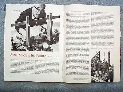
But as it is a useful development to let the modelmakers reduce the essential information – land contours, building and equipment – into a model scaled to 1 inch per 200 feet.
The three-dimensional result is more understandable than blueprints, particularly to the non-engineers among the executives.
For this reason more and more big projects are starting off in a small way as steel models its future in miniature.
When
a new mill is under study the first step, often as not, is to build it in model form.
While it may seem an easy matter to “build” a small version of a giant mill, the same kind of engineering know-how, the same attention to detail
plus craftsmanship
worthy of a watchmaker are required of the model builders.
Their talents are not restricted to duplicating the overall facility in miniature.
For when they build a plant to scale they usually equip it with model furnaces, rolling mills, overhead cranes and perhaps
machine tools and other auxiliary equipment.
These are created in tiny forms, sometimes with
moving parts, often
involving the use of clock gears to give a realistic appearance.
…
The training director of a large steel company points happily to his experience with a 38-foot model of a steel rolling mill built months in advance of the actual half-mile-long mill which
went into operation last December.
N conjunction with the model,
a full-scale mock-up
of the controls was made available for training the ill
crews.
Because the men were thoroughly familiar with
the
mill’s sequence of operations and had experience with it through mock-up and model they produced high quality steel sheets almost from the start of commercial operations.
There was very little of the trial-and-error often encountered in getting the best out of a new facility.
CAPTION:
Engineers study model to check construction progress of a basic oxygen steelmaking plant.
Even before construction of a new hot strip mill was completed, mill crews gained production experience through training on a scale model.
…
A taught string, run from the hole to all the equipment a real worker will control, determines true sight lines indicating whether a man will have an unobstructed view of what he needs to see to do his job.
Plant safety directors use models, too.
For example, stairs and handrails that seem o present no
hazards as they appear in the blueprints may show up in three-dimensional miniature as too narrow, or too steep, or not providing enough headroom under a pipe.
This usage leads to still another advantage of models over blueprints – even for trained industrial, civil and design engineers.
Accustomed as they are to reading technical drawings, many may fail to “see things that aren’t there.”
It would be more than embarrassing to plan a new facility in a building and then discover that there wasn’t enough room in the basement to accommodate the necessary pipe and conduit.
Models of the labyrinthine underground not
only aid in planning but also serve as “keys” to help maintenance men locate trouble spots long after the equipment is in operation.
“Working models” with their moving parts have an attraction for laymen far beyond the more prosaic, static miniaturizations.
Even so they are much
more than toys to steel men.
…
Paul Steiner, a leading independent modelmaker for industry, points out that he employs 12 skilled specialists who put in 24,000 manhours a year creating models for his steel company clients alone.
Facts and figures at his fingertips, he shows that he can produce a model of a mill from blueprints in about three months, compared with three years for the full-sized facility.
The cost of the model, usually ranging from ,000 to ,000, will be approximately one-twentieth of one percent that of the actual mill.
…
One of the more dramatic examples of what he means was shown recently in models of a proposed mass transit system for congested metropolitan areas.
Civic authorities and the general public could see the ultra-modern subway cars n their tunnels.
Furthermore, cutaway models of the topography made it possible for them to see construction details of te underground passageways, complete with stations.
…
“Models are the universal language,” according to one steel plant engineer.
“they make sense, whether seen through the eyes of technically trained men like me, or financial men, or mill workers, or sales representatives.
SIC TRANSIT
by William V. Adams
Hoots and laughter from a delighted throung of New Yorkers filled the chill November air as top-hatted and bearded city councilmen scrambled frantically out of the six doors of an oddly-shaped horse drawn carriage.
The tongue of one carriage had crashed through the rear of an identical vehicle ahead on the maiden run of the world’s first street car line.
Nevertheless this 183 attempt to solve the perpetual problem of city transit was hailed by Mayor Walter Browne as “the greatest achievement of man.”
The cars bore the name “John Mason” in honor of the prominent banker who had conceived the idea of “coaches mounted on iron wheels drawn by horses over iron rails.”
They also bore the
name of the builder, John Stephenson, a young coachmaker.
The first cars resembled stage coaches except that each had three compartments and ran on flanged iron wheels.
Each compartment was designed to accommodate ten persons, though not unlike today, when the line was in actual operation the compartments held as many passengers as could fight their way
in and the roof was usually filled too.
The car bodies were of wood, and leather straps provided the spring suspension of the day.
There was a foot brake for the driver.
Almost a mile of track
had been laid on Fourth Avenue.
The “tracks” were granite blocks grooved to hold the flanges of the car wheels.
The wheel treads rode on an inch-wide iron strap bolted next to the groove.
For the inaugural run the city councilmen boarded the first car and the officers of the railroad the second.
As a safety demonstration, both cars were to stop short at a signal.
Whips cracked and the cars were soon rumbling along at about ten miles an hour.
At the signal to stop, lead driver Lank O’Dell reined in his dappled grays and hit the brake.
But the rattled driver of the second car merely cried, “Whoa.”
The horses alone couldn’t stop the heavy car.
The center pole pierced the rear of the leading vehicle, ruffling the local dignitaries.
The resulting confusion gave the
amused spectators a view of their
city government in action.
John Stephenson became the world’s foremost builder off horse cars.
His cars were common in the cities of Europe, South America, China and Japan
as well as North America.
He attributed his success to the fact that the used only American materials.
American irons were tougher, he claimed, than the English and could provide the same strength with less weight.
His success is more probably attributable to his flair for design, technical improvements and honest craftsmanship.
He held many patents including one signed by President Jackson and his cabinet.
The horse car became a thing of the past after World War I, but the longsuffering transit passenger is still with us in ever increasing numbers.
City fathers across the country are taking
a hard look at the problems of mass transit, and well they
might.
Today seventy percent of our population lives in urban areas and some experts predict that this may rise to ninety percent before 1980.
A new concept of rapid transit, one system to serve a whole metropolitan area, is being pioneered by San Francisco.
A study is being made of the feasibility of linking the east coast megalopolis from Boston to Washington by a super transit system.
There is a new look in equipment, too, and the look is steel.
Stainless steel cars running through steel tunnels and over steel trestles will stop at steel stations.
There is hope for the straphanger, if he can just hang on a little longer.
All these brochures were found in my uncle's / grandmother's attic.
My uncle began collecting these from dealers about age 13.
Combined items reduces total shipping cost. I will combine into a 1 package weight shipping.
I use a sheet of cardboard so these don't get bent.

